IHS Logo

The Institute of Health Systems

Environmental Monitoring of Urban Lakes in Hyderabad Metropolitan Development Area (HMDA).

Urban Lake Water Quality Monitoring in HMDA Area.

Nurturing and protection of urban water bodies is important for healthy neighbourhoods and sustainable cities. Smart cities rely on field data and information gathered from multiple sources to manage urban ecosystem, improve operations and enhance quality of life.

Urban water bodies in the Hyderabad metropolitan area consist of many small to medium sized lakes and irrigation tanks that were built primarily for irrigation and/or fisheries. Many of these water bodies were part of cascading chain tank systems designed to conserve water. Urbanisation poses a challenge for these water bodies. Protection and maintenance of tanks for irrigation takes a backseat due to changing land use from agriculture to residential, institutional and industrial purposes. So, yesteryears irrigation tanks and lakes have become urban lakes and water bodies. Though relatively small in size, these urban lakes are important environmental, social, and economic assets. Juxtaposed with conventional utility for irrigation and fisheries, new uses such as recreation, tourism, and water sports appear. Concomitantly, urban water bodies face existential threats and new challenges, such as the vulnerability of encroachments and pollution.

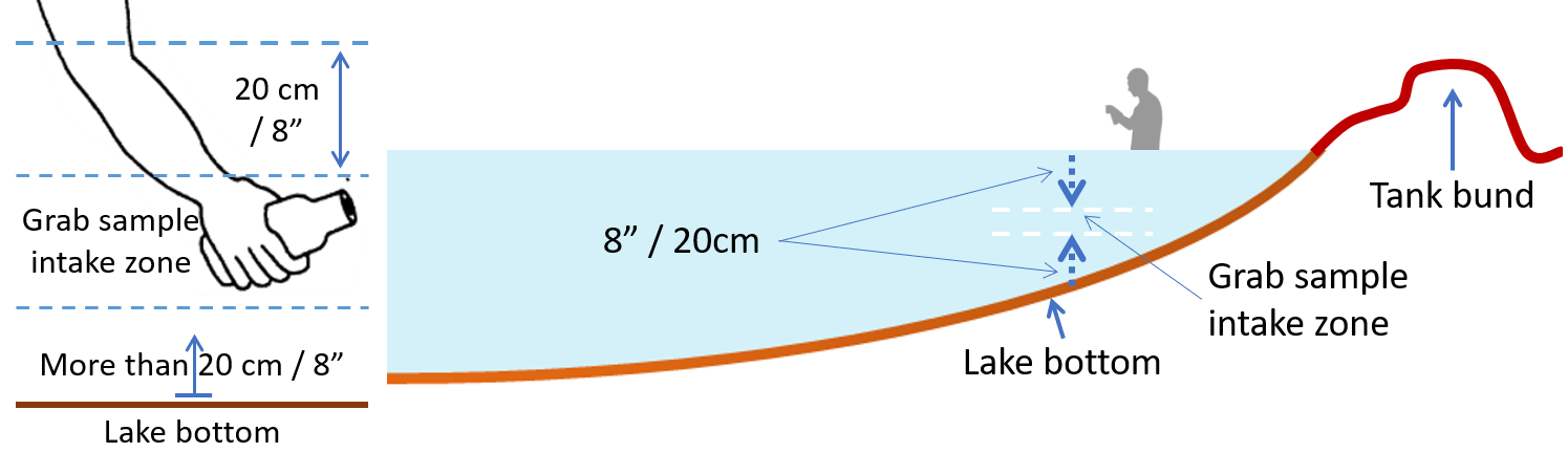
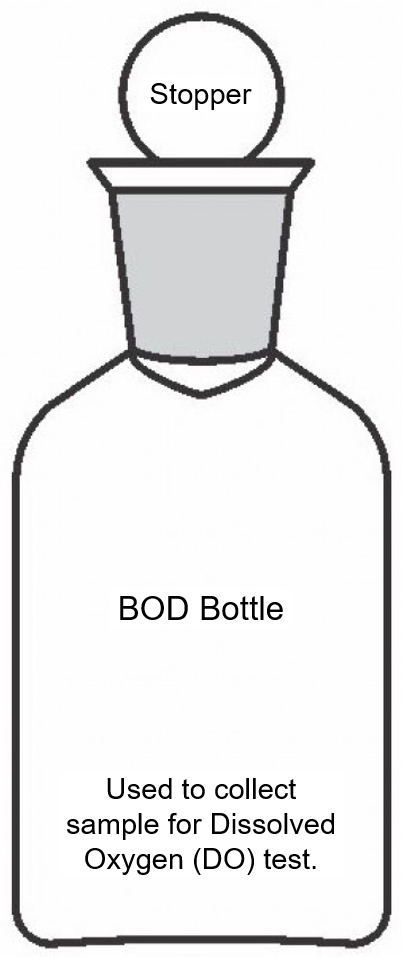
Field observation of the urban water bodies and monitoring of their water quality provides a basis and required data for effective protection and nurturing of the water bodies for contemporary public uses and to improve overall environment of the city. To facilitate monitoring of water quality in water bodies in and around Hyderabad, the IHS has developed a Tank/Lake Water Sample Collection Guide.

IHS Guidelines for Collection of Water Samples from Urban Water Bodies, Tanks and Lakes.

(IHS - Tank/Lake Water Sample Collection Guide.)

  1. During the course of perambulation, identify main part of the lake area. Figure 1 shows various parts of a lake area labelled on a snip of Google earth map showing the Rudraram village lake in HMDA area. Almost all lakes in Hyderabad area have an embankment popularly referred to as ‘tank bund’. First identify the ‘tank bund’ which would be the deep end of the lake and foreshore areas, which would be the submersible area when the tank if full. Foreshore areas are usually opposite side of tank bund. Identify left and right sides of the lake in question by positioning yourself on the tank bund and looking towards the lake water body.
  2. Figure 1: Identification of Lake Parts. Illustration using a snip of Rudraram village lake from Google earth map.
    Identification of Lake Parts. Illustration using a snip of Rudraram village lake from Google earth map.
    The map snip has been rotated 180° to facilitate visualisation from the perspective of the tank bund.
    Source of base layer: A snippet from Google earth map accessed on 17 Aug 2022.
  3. Identify the inflow channels, which would mostly be in the foreshore area. The inflow channels may not always have water. However, one can identify these by observing the troughs in the foreshore area, dampness and growth of vegetation along the route of inflow channels.
  4. Many lakes would have built surplus weirs over which surplus water flows into outlet channel. Where, there is no surplus channel, surplus water would flow over flanks of the tank bund. The outflow channel would be somewhere on downstream side of the tank bund.
  5. Three different sampling points have to selected for collection of midstream (deep-end), inlet and outlet samples.
    1. Deep-end: This would be the around middle part of the tank bund. Look for points on the tank bund where people usually enter into the lake. For example, a bathing. It will be easier to wade into the lake at such a point, with minimal disturbance to the lake bed.
    2. For the inlet sample: Select a suitable point along the foreshore, left or right sides.
    3. For the outlet sample: Select points immediately downstream of surplus weirs if any. If there is no surplus weir, and/or there is no flow over the surplus weir, select a sampling point along left or right side of the lake, avoiding the side from which inlet sample is taken. Thus, if inlet sample is taken from left side of lake, then select a suitable point on right side for outlet sample.
  6. Figure 2: Collection tray, set of four sampling bottles and cool box for preservation and transport of samples after collection.
    Identification of Lake Parts. Illustration using a snip of Rudraram village lake from Google earth map.
  7. 5. Field observation, sample preservation kit:
    1. Thermometer to measure lake water temperature (Hanna HI145-20 T-Shaped Celsius Thermometer with 300mm probe). The probe should have a marking to indicate 20cm from the tip (Figure 7).
    2. Figure 3: T shaped 30cm-long probe thermometer with paint mark at 20cm.
      T shaped 30cm-long probe thermometer with paint mark at 20cm.
    3. Collection tray (LWH: 30cm X 26cm X 6cm). One tray per team. Same tray can be reused at every sample collection point.
    4. Cool box (LBH:35cm X 27cm X 24cm; 14L Ice box), 3 per lake. Use one of the three cool boxes to carry cooled ice packs from office to the field, for preservation of samples from all three sampling points.
    5. Dissolved oxygen (DO) fixing reagents in a spill proof box.
    6. Figure 4: Container box to hold DO fixing reagent bottles, sampling bottles and fixing reagent box in collection tray, and carry basket.
      Identification of Lake Parts. Illustration using a snip of Rudraram village lake from Google earth map.
    7. Protective glass. Two pairs.
    8. Nitrile hand gloves.
    9. Water proof marker.
    10. Four pieces of one inch diameter, 4ft long PVC/CPVC pipes with thread and couplings. The pipes should be numbered serially with permanent marker to be joined in the field. Joined pipes should be marked with permanent markers to indicate ½ metre, 1 metre and 1.5 metre marks, to measure depth of water. Disassemble pipes after use for easy transportation inside vehicle.
    11. Measuring tape to measure exact water depth from water mark on PVC pole or any other locally arranged pole.
    12. Carry basket (LBH: 29cm X 22cm X 19cm) to hold sampling tools, kits a and supplies (for example; gloves) etc.
    13. Flow measurement device.
    14. The field observation and sample collection team will use their smartphones to read GPS coordinates.
  8. Reading Latitude and Longitude (GPS coordinates at any point:
    1. Stand at the point where you want to measure GPS coordinates. Prefer a point where there is no obstruction to the sky.
    2. Use your smartphone.
    3. If you have a special app to read longitude and latitude, use the same.
    4. If you have Google Map app on your phone, you may use the same. To find out your current coordinates, zoom into your location and hold down on the touchpad screen in the map for some time and release. Your latitude and longitude will pop up in the search bar for you to read.
  9. Preparations before wading into the lake for collection of samples:
    1. Both the sample collector and associate are required for this operation.
    2. Place the collection tray on level ground near the sampling point and arrange the sample collection bottles in the following serial order.
      1. 250 ml clean sterile bottle (CSB) for bacteriological analysis; labelled as ‘A’.
      2. 1000 ml clean and dry standard size bottle (CBWS) for COD & BOD; labelled as ‘B’.
      3. 1000 ml clean and dry standard size bottle (CBWS) for other chemical parameters; labelled as ‘C’.
      4. 300 ml glass stoppered BOD bottle (BODB) for dissolved oxygen; labelled as ‘D’.
    3. Write the Lake Id and sampling point on each of the four bottles using a waterproof marker.
    4. Record the bottle ids under concerned sampling point of the lake observation form.
    5. Place the following DO sample fixation reagents on a separate tray or in the field reagent box, nearby the collection tray.
    6. Have the ice packs and cool box ready for preservation of the samples. Use separate cool box for each sampling point.
  10. General procedure for grab sample by the hand-dip method.
    1. Have the associate ready behind you to take notes, pass on and receive sample collection bottles, one after the other until all sample collection bottles meant for the sampling point, are filled.
    2. Remember that mouth of the dipped bottle should not go too close to the lake bottom. The ideal depth zone for intake of grab sample would be at least 20 cm above lake floor and 20 cm below surface (Figure 5 & Figure 7). Thus, the depth of water at the sampling point should be at least 2ft, so that there is about 10 cm of intake zone.
    3. Figure 5: Sample intake zone and grab sample collector’s orientation for lake water quality testing.
      Sample intake zone and grab sample collector’s orientation for lake water quality testing.
    4. Carefully wade into the lake and stop at a point where water is knee deep. Stand facing the lake (Figure 4). Stand still for some time, until kicked up sediments (Figure 5) settle down. During this time, you may read GPS coordinates, measure subsurface temperature as well as pH and relay the information to your companion to record. Alternatively, you can read GPS, temp & pH after collection samples. See details in para 12 below.
    5. Figure 6: Sediments on a lake floor stirred up by wading-in of a sample collector.
      Sediments on a lake floor stirred up by wading-in of a sample collector.
    6. Face towards the lake centre (deeper area). You will need to bend forward to collect sample from a point that has not been disturbed by your entry into the lake (Figure 4).
    7. Clear floating matter, if any, from the sampling point by creating a gentle ripple to push floating matter away.
    8. Grasp the sample container near the base of the bottle, in one hand.
    9. Open the cap and hold it in the other hand.
    10. Hold the bottle towards deeper part of the lake, tilt it downwards and plunge the bottle opening under the water surface, until your elbow touches water surface.
    11. Avoid contact with the lake floor during this process (Figure 5).
    12. Turn the submerged bottle gradually as your elbow makes 45° angle with respect to water surface, and the opening pointed away from you, towards deeper areas of the lake.
    13. Fill the bottle slowly, allowing air inside the bottle to escape gradually. As the bottle fills more and more, gradually turn the bottle up until its mouth looks up vertically upwards, while still under water.
    14. In case of first three bottles (labelled ‘A’, ‘B’ & ‘C’); lift the bottle gently (to avoid disturbance of the sampling for subsequent sampling), discard a little bit of the sample to allow for some air gap under the neck, cap the bottle and pass on to associate for placement in sample transportation tray/box.
    15. In case of the last bottle (labelled ‘D’) and meant for dissolved oxygen (DO), you need to cap the bottle securely under water. See more details in para 9 below about sample collection for DO.
  11. Sample collection for Dissolved Oxygen:
    1. Use the BOD bottle labelled as ‘D’. BOD bottles have a ground glass stopper that fits tightly into ground glass neck of the bottle. When closed, these are air tight bottles would not allow any exchange of atmospheric oxygen. This same bottle is used in the laboratory to incubate prepared solutions in the BOD test process, hence the name. Note that samples for BOD need not be collected in BOD bottle. But samples for laboratory testing of dissolved oxygen must be collected in BOD bottle, fixed on the spot, and the closed BOD bottle transported to the laboratory.
    2. Remember that the water sample must be collected in such a way that you can replace the bottle stopper while it is still submerged. That means that you must be able to reach into the water with both arms and the water must be deeper than the sample bottle.
    3. Remove the stopper of the BOD bottle. Slowly lower the bottle into the water, pointing it downstream, until the lower lip of the opening is submerged in the grab sample intake zone. Allow the water to fill the bottle very gradually, avoiding any turbulence. Turbulence would add oxygen to the sample and adversely affect test result. Hence, gradual filling and avoidance of any turbulence is very important. When the water level in the bottle has stabilized (it won't be full because the bottle is tilted), slowly turn the bottle upright and fill it completely. Keep the bottle under water and allow it to overflow for 2 or 3 minutes to ensure that no air bubbles are trapped.
    4. Replace the stopper while the bottle is still submerged. Lift it out of the water and look around the "collar" of the bottle just below the bottom of the stopper. If you see an air bubble, pour out the sample and try again.
    5. Handover filled bottle to assistant for placement in a tray on the bank.
    BOD Bottle.
  12. Fixing the dissolved oxygen sample:
    1. "Fix" the sample immediately after collecting other grab samples from the same point and before moving on to other sampling points.
    2. Before fixing the sample, examine the filled BOD bottle for any bubbles that may have adhered to the walls. If any bubbles are present, the sample is discarded and drawn again.
    3. Remove the stopper and first add 2 ml of the first fixing reagent labelled – ‘M’ (Manganese sulfate) to the sample. Use the calibrated dropper provided with the reagent bottle. This reagent must be added slowly by touching the dropper tip to inside of the BOD bottle neck, so that the reagent flows in and mixes with sample without introducing any air bubble.
    4. Then, add 2 mL of the second fixing reagent labelled ‘I’ (alkaline iodide-azide solution) to the sample contained in the BOD bottle. This reagent must also be added gently by touching the reagent dropper to inside of sample bottle-neck and gradually releasing the reagent.
    5. Replace stopper of the BOD bottle immediately and mix the contents thoroughly.
    6. An orange-brown flocculent precipitate will form if oxygen is present.
    7. Wait a few minutes until the floc in the solution has settled.
    8. Place the bottle in cool box for preservation and transportation to the laboratory.
  13. Caution about handling of the fixing reagents:
    1. Both fixing reagents [manganous sulfate solution (labelled – ‘M’) and alkaline-iodide-azide (labelled ‘I’)] are;
      1. Harmful in contact with skin;
      2. Can cause severe burns and eye damage; and
      3. Harmful to fish in lake.
    2. So, handle the reagent bottles carefully and comply with following safety precautions:
      1. Wear protective glass and hand gloves.
      2. Place the reagent bottles in a firmly seated tray and do not spill the reagent.
      3. Draw required volume, inject into the sample bottle, replace the calibrated dropper with cap and close the cap as soon as possible.
      4. First aid in case of skin contact: rinse and wash with plenty of soap and water; Take off contaminated clothing, if any and wash in water.
      5. First aid in case of eye contact: Rinse cautiously with bottled water for several minutes. Remove contact lenses, if any, and continue rinsing with bottled water.
  14. Recording of GPS coordinates, temperature and pH:
    1. After wading into the lake up to be sampling point, you are going to stand still for some time for the disturbance to settle down. Use this time to read GPS coordinates and relay the same to your associate for recording. If, on the other hand, it is not safe to carry your smartphone up to the sampling point, this step may be omitted and GPS coordinates may be recorded at the bank where you would have set up the sample transportation box/tray.
    2. Measure lake water temperature at a depth of 20 cm (8”) below surface by dipping the thermometer probe to desired depth.

Updated on 17-03-2024